IMS printed circuit boards as a new manufacturing technology.
High-intensity LEDs are penetrating the lighting market more and more. High efficiency, ideal light spectrum, compact design are just a few of the aspects with which LEDs can score points compared to previous light sources. A serious disadvantage, which is often of little interest to operational planners, is the necessary low operating temperature of this technology. The light and with it the heat loss arise at certain points. The heat has to be dissipated quickly, because at an ambient temperature of 80 – 90°C most semiconductors reach the limits of their resilience.
If a power semiconductor can no longer dissipate the generated heat loss via its own housing, it is usually equipped with a heat sink. If the heat sink is sufficiently dimensioned, this passive cooling is sufficient. Otherwise, a fan, for example, provides additional cooling. Other measures are for e.g. heat pipes.
Heat dissipation generally occurs in two ways. On the one hand by heat radiation, on the other hand by heat convection. In thermal radiation, energy is transferred from the hot body to a more distant body in the form of infrared (IR) light. The medium between the bodies does not play a decisive role. For example, the sun’s IR radiation bridges the vacuum between the star and our earth. Heat convection works quite differently. Here, a carrier medium absorbs the thermal energy and transports it further. According to this principle, in a central heating system, for example, a liquid or gaseous medium transports the heat from the boiler to the radiators.
When developing electronic devices, the focus of the housing designers is rarely on the heat loss to be dissipated. The focus is much more in the aesthetic area. Therefore, the electronics developer has to deal with the topic of heat management. This often leads to insurmountable contradictions, e.g. maximum performance with minimum volume. In this case, that means everything that is available is used as a heat sink – including the circuit board.
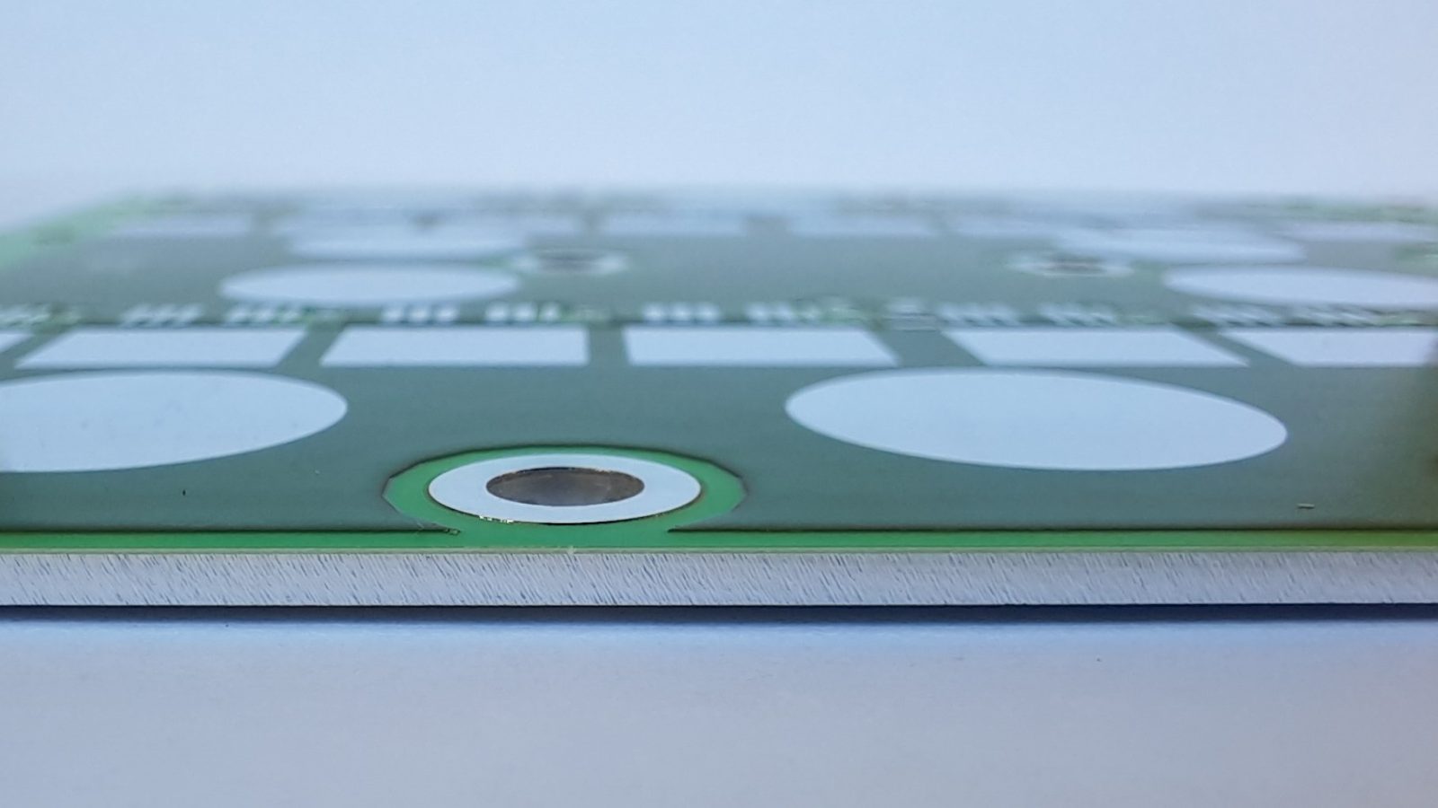
Traditionally, passive heat dissipation through a circuit board is largely limited to convection using ambient air and thermal radiation. The FR4 base material also acts as a thermal insulator and the conductor tracks themselves can only dissipate little heat due to their low mass. This is partly reflected in partially discolored temperature hotspots. In order to be able to dissipate heat more efficiently, the thermal conductivity of the carrier medium must be increased and its volume maximized. This is achieved using so-called aluminum core or IMS circuit boards (Insulated Metal Substrates). The actual carrier material (usually FR4) is replaced by aluminum. Depending on the requirements, aluminum thicknesses of 0.2 – 2.0 mm are standard. The entire circuit board has this aluminum core and acts like one large heat sink. The avoidance of heat hotspots achieved in this way has a massively positive effect on the service life and reliability of the subsequent assembly.
IMS circuit boards consist of a pure aluminum core, which is separated from the circuit pattern by an insulating layer. The conductive pattern is usually made of copper, but can be provided with all other available surfaces. The manufacturing processes are largely the same as in standard production. Special aluminum drilling and milling machines are only required for mechanical processing using CNC machines. These special machines, which have a cooling and lubricating device, were specially purchased at Becker & Mueller in order to be able to face these new market requirements.
It makes sense that only the power section of a circuit is placed on such an aluminum core circuit board. This prevents the control part from heating up. Rigid-flex circuit boards can now also be made from IMS – in conjunction with flexible polyimide and, if necessary, an additional FR4 base material.
The design rules for IMS PCB differ somewhat from standard production. When it comes to the drill hole spacing, for example, greater security must be planned, since the through-connection to the aluminum core must be insulated. The insulation is provided by resin, which covers the holes in the IMS board during lamination. The components can be mounted directly on the IMS PCB during assembly. Appropriate clearances are implemented in the heat-conducting prepreg for this purpose.
In addition to this aluminum core technology, printed circuit boards with copper inlay technology (Cu inlay technology) can also be used. There, the printed circuit boards are partially provided with thick copper strips (more on this here).